Difference between revisions of "XPS50P50"
From CPS Technical Wiki
(→Wiring diagrams) |
(→Connector pinouts) |
||
| Line 11: | Line 11: | ||
! Pin !! Name !! Function !! Usage | ! Pin !! Name !! Function !! Usage | ||
|- | |- | ||
| − | | 1|| RETURN|| Signal ground|| Ground reference for meter outputs (kV MON, mA MON) | + | | 1|| RETURN|| Signal ground|| Ground reference for meter outputs (kV MON, mA MON) |
|- | |- | ||
| 2|| kV MON|| HV meter (out)|| 0 to +10 V = 0 to +50 kV out | | 2|| kV MON|| HV meter (out)|| 0 to +10 V = 0 to +50 kV out | ||
| Line 21: | Line 21: | ||
===Control (J2)=== | ===Control (J2)=== | ||
| + | |||
| + | {| class="wikitable" | ||
| + | |- | ||
| + | ! Pin !! Name !! Function !! Usage | ||
| + | |- | ||
| + | | 1|| VREF|| 10V reference (out)|| Reference voltage for external circuitry; 10 mA maximum. | ||
| + | |- | ||
| + | | 2|| NC|| No connect|| | ||
| + | |- | ||
| + | | 3|| ISET|| Beam setpoint (in)|| Beam control voltage: 0 to +10V = 0 to 1 mA out. Local control: connect to pin 4. Remote control: connect to external 0 to +10V source. | ||
| + | |- | ||
| + | | 4|| IPOT|| Beam control pot (out)|| Local control: connect to pin 3. Remote control: leave disconnected. | ||
| + | |- | ||
| + | | 5|| NC|| No connect|| | ||
| + | |- | ||
| + | | 6|| VSET|| HV setpoint (in)|| HV control voltage: 0 to +10 V = 0 to +50 kV out. Local control: connect to pin 7. Remote control: connect to external 0 to +10V source. | ||
| + | |- | ||
| + | | 7|| VPOT|| HV control pot (out)|| Local control: connect to pin 6. Remote control: leave disconnected. | ||
| + | |- | ||
| + | | 8|| RETURN|| Signal ground|| Ground reference for VREF, VPGM and IPGM. | ||
| + | |- | ||
| + | | 9|| RETURN|| Signal ground|| Ground reference for VREF, VPGM and IPGM. | ||
| + | |} | ||
==Wiring diagrams== | ==Wiring diagrams== | ||
Revision as of 16:21, 7 December 2021
This is the wiki page for CPS model XPS50P50.
Contents |
Connector pinouts
Monitor (J1)
This connector provides access to metering output signals and the safety interlock input signal.
| Pin | Name | Function | Usage |
|---|---|---|---|
| 1 | RETURN | Signal ground | Ground reference for meter outputs (kV MON, mA MON) |
| 2 | kV MON | HV meter (out) | 0 to +10 V = 0 to +50 kV out |
| 3 | mA MON | Beam meter (out) | 0 to +10 V = 0 to 1 mA out |
| 4 | INTLK | Safety interlock (in) | Short to pin 1 to enable HV output; leave open to disable HV output |
Control (J2)
| Pin | Name | Function | Usage |
|---|---|---|---|
| 1 | VREF | 10V reference (out) | Reference voltage for external circuitry; 10 mA maximum. |
| 2 | NC | No connect | |
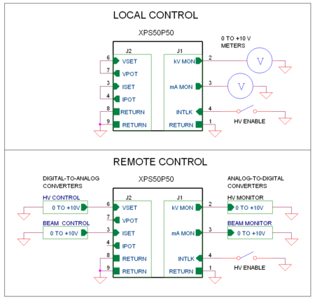
| 3 | ISET | Beam setpoint (in) | Beam control voltage: 0 to +10V = 0 to 1 mA out. Local control: connect to pin 4. Remote control: connect to external 0 to +10V source. |
| 4 | IPOT | Beam control pot (out) | Local control: connect to pin 3. Remote control: leave disconnected. |
| 5 | NC | No connect | |
| 6 | VSET | HV setpoint (in) | HV control voltage: 0 to +10 V = 0 to +50 kV out. Local control: connect to pin 7. Remote control: connect to external 0 to +10V source. |
| 7 | VPOT | HV control pot (out) | Local control: connect to pin 6. Remote control: leave disconnected. |
| 8 | RETURN | Signal ground | Ground reference for VREF, VPGM and IPGM. |
| 9 | RETURN | Signal ground | Ground reference for VREF, VPGM and IPGM. |
Wiring diagrams
Model XPS50P50 can either be controlled locally, by adjusting its internal trimpots, or remotely by connecting it to external programming voltages. In both cases, the output voltage and beam current may be externally monitored by connecting meters (or digital-to-analog converters) to J1 pins 2 and 3.
